Electron Spin Resonance (ESR)
Caltech Senior Physics Laboratory Experiment 6, September
1997
Electron Spin Resonance (ESR), often called Electron Paramagnetic Resonance
(EPR), is similar to Nuclear Magnetic Resonance (NMR), the fundamental
difference being that ESR is concerned with the magnetically induced splitting
of electronic spin states, while NMR describes the splitting of nuclear
spin states. In both ESR and NMR, the sample material is immersed in a
strong static magnetic field and exposed to an orthogonal low- amplitude
high-frequency field. ESR usually requires microwave-frequency radiation
(GHz), while NMR is observed at lower radio frequencies (MHz). With ESR,
energy is absorbed by the sample when the frequency of the radiation is
appropriate to the energy difference between two states of the electrons
in the sample, but only if the transition satisfies the appropriate selection
rules. Splitting can occur only when the electron is in a state with non-zero
total angular momentum, i.e. electrons in atoms with closed atomic shells
cannot show this behavior. The term ESR refers specifically to the case
in which the spins of the electrons absorbing the radiation are only weakly
interacting ("weakly coupled") with each other. In NMR the static magnetic
field splits the quantum states of a nucleus which has non-zero nuclear
spin. The observation of NMR requires that the total electronic spin be
zero. Why? (Read Feynman's discussion of NMR, Vol. 2, 35-6.)
Our experiment makes use of a bulk sample (as contrasted to Rabi's molecular
beam resonance method discussed in Feynman), and is limited to those materials
that have electrons with non-zero total angular momentum (or a "dipole
moment"). Because of chemical binding, most materials in bulk form do not
have net electronic angular momentum, and thus are not suitable for this
experiment. Some materials which are suitable are:
-
Atoms or ions of the transition elements which contain unpaired 3d electrons
inside the completed 4s shell. This experiment will allow you to examine
the elements Mn++ and either Cr+++ or Fe+++
as dilute impurities in a MgO host crystal.
-
A small number of organic molecules are called free radicals because they
contain a single unpaired electron, aa-Di-phenyl-b-picryl-hydrazyl (DPPH)
being the one that will be used as a calibration source for this experiment.
All but one of the electrons of this molecule are paired so there is only
the orbital and spin motion of one electron present per molecule. In fact
the orbital motion of that electron is quenched. (Refer to C. P. Slichter,
Principles of Magnetic Resonance - page 65ff). The spin motion of
this single unpaired electron gives to this molecule a g-factor that very
nearly equals that of a free electron; g = 2.0038 instead of 2.00232.
THEORY
1. ENERGY LEVEL STRUCTURE:
If a paramagnetic atom or molecule is placed in a solid there will be interactions
between it and its surroundings. In the case we will examine, the result
of these interactions will be to leave the single paramagnetic electron
in a state which appears similar to that of an s - state electron, which
has zero orbital angular momentum and therefore allows us to examine the
effect of a magnetic field on the spin motion.
The paramagnetic atom or molecule has a quantum state determined by
the Hamiltonian, which contains several terms. The dominant potential term
is the Coulomb interaction between the paramagnetic electron and the electrons
of its own atom, the neighboring atoms, and the positive charges of its
own nucleus. This large Coulomb interaction defines the basic ground state
for the electron. The remaining terms can be considered as perturbations.
Assuming that the effect of the Coulomb terms has been to leave this
electron in an L=0 (quenched orbital motion) state, the magnetic perturbation
Hamiltonian can be written:
 The total electron angular momentum quantum number J is just the spin quantum
number, S, in this case. The nuclear angular momentum quantum number I
is determined by the net spin of the nucleus. The first term is the hyperfine
interaction, and in this case (L = 0) is the "Fermi Contact" term. The
second term is the electronic Zeeman term due to the effect of the applied
magnetic field H0 on the electron spin. The third term is the nuclear Zeeman
term due to the effect of the magnetic field on the nuclear spin. Since
betaN is much smaller than beta, this last term is small. The
magnetic field HN seen by the nucleus may be modified by the
electron system. Beta and betaN are the electron and nuclear
"magnetons" beta = e hbar / (2mc).
The electron's 'g' factor is given by the Landé rule for the
vector model of the atom. The nuclear 'g' factor, gN, is obtained
from a knowledge of the structure of the nucleus.
With fields of the magnitude used in this experiment (several kiloGauss),
F = I + J is not a good quantum number. Energy splittings due to the applied
field are comparable to, or larger than, the energy splittings between
different F states. Put another way, the states of total F are "mixed"
by the applied field, and thus F is not a good description of the state
of the system. However, J = L + S is a good quantum number, for even at
fields of the magnitude used here, the spin-orbit splitting is much greater
than the splitting due to the applied field.
Thus the good quantum numbers for use in this experiment are J
and I, and their projections along the field axis. The energy levels of
a paramagnetic ion in a magnetic field of the magnitude available to this
experiment will be dependent on the values of MJ and MI,
as illustrated for Mn++ in Figure 1.
Mn++ is the manganese atom with two 'd' electrons missing
from the 3d shell. This leaves 5 electrons in the 3d shell (half - filled).
The ground state for this case is that in which all 5 electron spins are
parallel, i.e.,6S5/2. Since the nuclear spin I = 5/2, the total
quantum number F = I + S (since L = 0), ranges from 0 to 5. Figure 1 shows
the splitting of just the S = 1/2 component. The other spin components
will split more rapidly with magnetic field than does the S = 1/2 component,
but the allowed transitions will be degenerate with those for S = 1/2,
so only 6 lines will be seen in the spectrum.
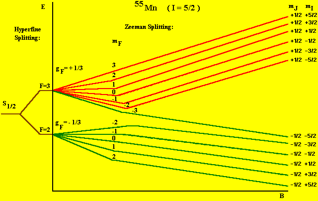 S=1/2. L=0, J=1/2, I=5/2
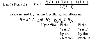 Figure 1: Hyperfine Splitting
2. WIDTH OF ABSORPTION PEAKS:
The width of the absorption peak in ESR is very much greater than in NMR.
This width arises from the spin-spin interaction between neighboring atoms.
In a sample containing N spins per cm3 (e.g., N DPPH molecules
per cm3 with one unpaired electron per molecule), each acting
as a dipole of strength m, the field H at any spin is the sum of the applied
field plus that due to neighboring spins:
 Spins throughout the sample see a field varying between H0 +
µ N and H0 - µ N, giving rise to a "line width",
just as if the external field were non-uniform. For nuclear spins we find
that:
 while for electronic spins;
 The breadth of the ESR lines makes them difficult to observe unless the
applied field is quite large. (Why not reduce N?)
In some materials, DPPH for one, the line will not be this broad. In
DPPH, the single unpaired electron wave function extends over the entire
volume of the molecule, which is about 10-7cm in diameter. Furthermore,
in a solid material, the exchange integral between neighboring molecules
is large, and the electron is shared between neighboring molecules, as
in the hydrogen bond. This gives rise to "exchange narrowing", a quantum
phenomenon first described by Van Vleck (Phys. Rev., 74,
1168 (1948)). This "exchange narrowing" might also be called "migration
narrowing", and can be pictured classically by supposing that the electron
is smeared over a large region of many molecules. It sees an average H
field, averaged over many molecules, with fluctuations averaged to zero,
leaving only the applied field. Support for this explanation will be found
in the fact that, in a dilute solution of DPPH, the resonance line becomes
broader, presumably because the exchange integral is reduced due to increased
inter-molecular spacing. In DPPH crystals, such as you will use, the line
width is about 2.7 Gauss.
EXPERIMENTAL APPARATUS
This consists of an electromagnet with power supplies to generate and modulate
a uniform magnetic field of several thousand Gauss, as well as the components
that generate and detect microwaves.
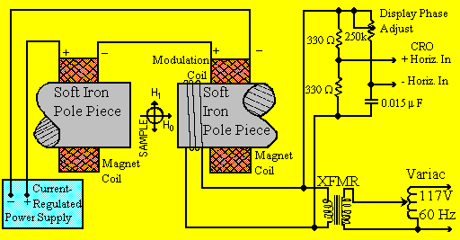 Figure 2. An ESR Spectrometer showing the sample, magnetic
fields applied to it, and the sources of these fields.
MAGNET:
A static magnetic field is provided by a 10 cm diam. electromagnet with
a current- regulated power supply (15 A Maximum). A 60 Hz AC component
is added to this field by an adjustable current through a winding on one
pole piece of the electromagnet. A voltage that is proportional to the
amplitude of this modulation provides the horizontal display for the CRO,
with provision for shifting the phase between the signal delivered to the
CRO and the modulation applied to the main magnetic field. As with an NMR
experiment, a homogeneous field is required for best results.
HALL MAGNETOMETER:
A Hall device, driven from a stable constant-current power system, with
a digital multimeter (DMM) reading the Hall voltage, is used to measure
the average value of the magnetic field applied to the ESR samples. The
drive current has been set to make the device direct-reading with an error
of < ± 3%, providing that the temperature of the Hall device
does not deviate significantly from normal (19-25 oC). The DMM must be
set to its 200 mV range (1 microV least significant digit) and carefully
"zeroed". Ignore the decimal point. Unit change in the least significant
figure will then be 1 Gauss. When making a measurement place the probe
as close to the microwave cavity wall as possible and away from the warm
magnet pole face.
MICROWAVE OSCILLATOR/DETECTOR SYSTEM:
The microwave system is contained entirely within the gap of the electromagnet.
See Figure 3. It consists of a short length of Ku (RG-53) rectangular waveguide
(12 GHz), short circuited at both ends to provide a relatively high-Q resonant
cavity. The samples to be investigated are mounted slightly off center
on a rotatable cylindrical plug whose end surface is flush with one end
of the cavity. This allows the samples to project slightly into the microwave
field of the cavity and their positions to be optimized for best signal-to-noise
ratio. A microwave Gunn diode is mounted along the center of the long axis
of the cavity, approximately 1/3 of the cavity length from the end opposite
the samples. The diode spans the short dimension of the rectangular waveguide,
efficiently coupling to the E vector of the microwave field, resulting
in maximum efficiency both in generating microwaves and in simultaneously
detecting the influence on that field by samples at resonance.
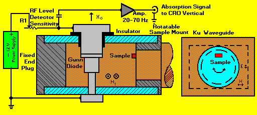 Figure 3. The Microwave Generator/Detector components.
GUNN DIODE:
A Gunn diode displays conductivity that is non-linear with applied voltage;
i.e., it has a negative-resistance V/I characteristic.
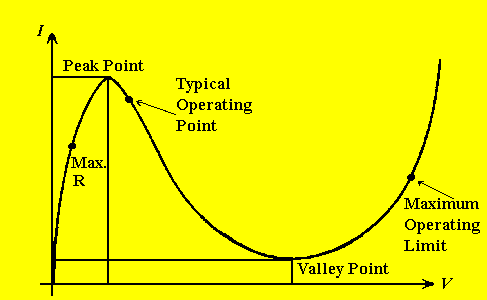 Figure 4. Characteristic V/I curve for a negative-resistance
device (Gunn diode).
The diode contains an extremely thin P-N junction diffused into a heavily
doped GaAs (Gallium Arsenide) substrate. The frequency of oscillation is
determined by the very high mobility of the electron/hole carriers in GaAs,
and the thickness of the junction. A benefit of the very thin junction
(10^-3cm) is that the conduction electrons are minimally affected by large
magnetic fields (4-5 kG).
The diode is powered by a stable regulated power supply and R1, a series
ten-turn variable 50 Ohm resistor. When Rl is set to its maximum (cw),
the operating point is to the left of the Peak Point. As this resistance
is reduced, the operating point moves to the right of the Peak Point into
the negative-resistance region where a microwave frequency of extreme spectral
purity is generated. Further reduction in series resistance increases the
power.
Because the Gunn diode acts simultaneously as both source and detector
of microwaves, optimization of the Signal-to-Noise Ratio is an interdependent
exercise. Both the level of microwave fields generated and the detection
sensitivity are affected by Rl. A 60 Hz signal, produced by
the reduction of the cavity Q when a sample absorbs energy at resonance
(a reduction in the microwave field level), is detected by the diode, and
amplified by a low-noise amplifier used to drive the vertical display of
the CRO. Detection sensitivity will be greatest when the operating point
is "marginal", just to the right of the Peak Point. The optimum requires
operation a bit farther into the negative-resistance region.
Samples in the cavity are DPPH plus trace quantities of several ions
of the 3d series (Mn++ and either Cr+++ or Fe+++)
diffused into a carrier lattice of crystalline MgO (Magnesium Oxide). The
field for one of the resonances depends slightly upon the orientation of
the crystal of MgO with respect to the magnetic field. Can you suggest
a reason for this?
EXPERIMENTAL TASKS
Equipment Turn-On Procedure:
Set the following controls as indicated.
-
Current Control: LOCAL
-
Tektronix 503 Oscilloscope: ON. Allow to warm up ~ 5 minutes.
-
Amplifier Power Supplies: ON
-
60 Hz Modulation: ON
-
KEPCO Power Supply: ON.
1. First set the 60 Hz modulation at maximum, and preset Rl
to its CLOCKWISE stop (maximum value of 50 Ohm). Force the diode to oscillate
by slowly rotating Rl COUNTER CLOCKWISE, i.e., reduce the value
of Rl. The onset of oscillations will be indicated by an abrupt
jump of the trace on the CRO. Sometimes the narrow trace will suddenly
be replaced by a broad vertical band of low-frequency waveforms ("squegging").
If the latter are seen, you have set the operating point almost exactly
on the peak point. Increase the level of oscillations slightly to restore
a thin trace with a bit of "grass" growing on it (thermal noise), then
slowly raise the magnet current until you locate the large DPPH peak and
then readjust the diode bias to get the best S/N. Note the effect of varying
the modulation amplitude and phase. Why are two peaks seen?
2. Use the Hall probe to measure H0 with the DPPH
peak centered on the trace, then calculate the frequency of the microwaves
by using the g-factor for DPPH (2.0038). Measure and explain the width
of the signal. (The Hall probe operating current has been set to make the
system direct reading, with an absolute accuracy of < 3%). When the
DMM is set to its 200 mV range, the least significant digit will equal
1 Gauss (ignore the decimal point). The Hall device has a substantial temperature
coefficient (~ -0.1%/Co), and should be exposed to the warm magnet pole
caps for the shortest practical time, and then removed to allow it to return
to "room temperature".
3. Measure the magnetic fields required to center all other peaks
on the CRO. Six are due to Mn++ while the others are due to
either Cr+++ or Fe+++. Try to determine which of
the peaks are due to Cr+++ or Fe+++. You will require
a knowledge of the electron configuration of both ions in order to do this
(the 'g' factor for Cr+++ in MgO is 1.9800 ± 0.0063;
and for Fe+++, 'g' = 2.0037 ± 0.0007).
Questions
-
The spin-orbit splitting scales as Z4. Use this to demonstrate
that J is indeed a good quantum number in fields of several kiloGauss,
as claimed. Why is this irrelevant in the case of 55Mn?
-
Use your knowledge of the selection rules for multi-polarities of radiation
to obtain the multi-polarity of the radiation absorbed by Mn++,
thus determining which energy level transitions will occur due to the applied
microwave radiation.
-
From your data, what are the 'g' and 'a' values for Mn++ in
MgO?
-
According to the quantum mechanical theory of the interaction of matter
and radiation, the rates for absorption and stimulated emission are exactly
equal. What must be true about the relative populations of the upper and
lower states in order for a net absorption of radiation to occur? Calculate
the difference in populations for H0 = 4 kG.
-
The ratio of the radiation frequencies employed in NMR and ESR is about
103, which, given the ratio of the nuclear and Bohr magnetons,
allows the use of the same field strength in both experiments. Why isn't
ESR examined with the SAME radiation as NMR (RF), but with a weaker magnetic
field? (This would have the considerable advantage of allowing the use
of a frequency counter to determine the radiation frequency.)
-
If you were to replace the existing Gunn diode with another that operated
at twice the frequency, how much increase in magnet current
would be required to re-establish resonance? (A semi-quantitative discussion
involving the magnetic properties of iron is desired!)
-
If you have an operating frequency of 12.5 Ghz in a rectangular cavity
that is 2 wavelengths long, what does the distribution of E and H fields
look like?
References
-
*A. C. Melissinos, Experiments
In Modern Physics, (Academic Press, 1966), Chap 8.
-
*The Self-Detecting Microwave Spectrometer, Western Electric, 1974.
(Reprint in Laboratory)
-
G. E. Pake, Paramagnetic Resonance, (W. A. Benjamin, 1962).
-
C. P. Slichter, Principles
of Magnetic Resonance, 3rd ed., (Springer-Verlag, 1992 and Harper
& Row, 1963), p. 65.
-
J. H. Van Vleck, Phys. Rev., 74, 1168, (1948).
-
Bowers and Owen, Paramagnetic Resonance II, Reports on Progress in Physics,
pp. 315-349, Vol. XVIII (1955). (Reprint in Laboratory)
-
W. M. Walsh, Jr. and L. W. Rupp, Jr. Review of Scientific Instruments,
42, 468, (1971). (Reprint in Laboratory)
-
R. P. Feynman, Lectures On Physics, Vol. II, Chap. 23 & 24.
-
Here is also a list
of WWW EPR/ESR sites.
* Primary reference.
Auf diesem Webangebot gilt die Datenschutzerklärung der TU Braunschweig mit Ausnahme der Abschnitte VI, VII und VIII.


